Hardware,
in detail.

A selection of engineering projects I’ve designed, implemented, and validated.

01 / FORMULA SAE SEP 2025 — 2026

Dash PCB

The Dash PCB was the first project I led on Illini Electric Motorsports. This board was in charge of communicating and providing power to the PLEX, our driver display, as well as handling auxiliary switch inputs and vehicle fault indicators. Since the PLEX operates on standard CAN while the car's buses are on CAN FD, the Dash PCB has to act as a bridge between the two protocols to allow for communication. Later in the year, after we found issues with our steering-angle sensor implementation, the scope of the project expanded to powering and providing private communication to the sensor so that it functioned without impacting the rest of our bus.
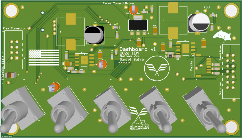
Front 3D view of the Dash PCB with auxiliary switches and mounted components
Dash PCB · front 3D view

System architecture

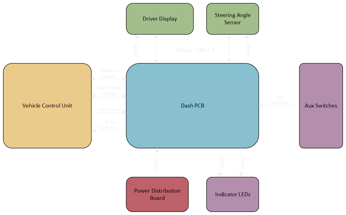
Dash PCB system architecture connecting the driver display, steering-angle sensor, vehicle control unit, auxiliary switches, power distribution board, and indicator LEDs
Dashboard system architecture

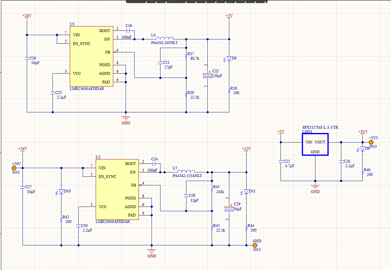
The dash PCB has to communicate with many different parts of the car. It receives 24 V power from our custom power distribution board and then steps that down to 12 V, 5 V, and 3.3 V with its internal buck converters and LDOs. This power is used both by the internal components, and as outboard power for the SAS (steering-angle sensor) and PLEX display.

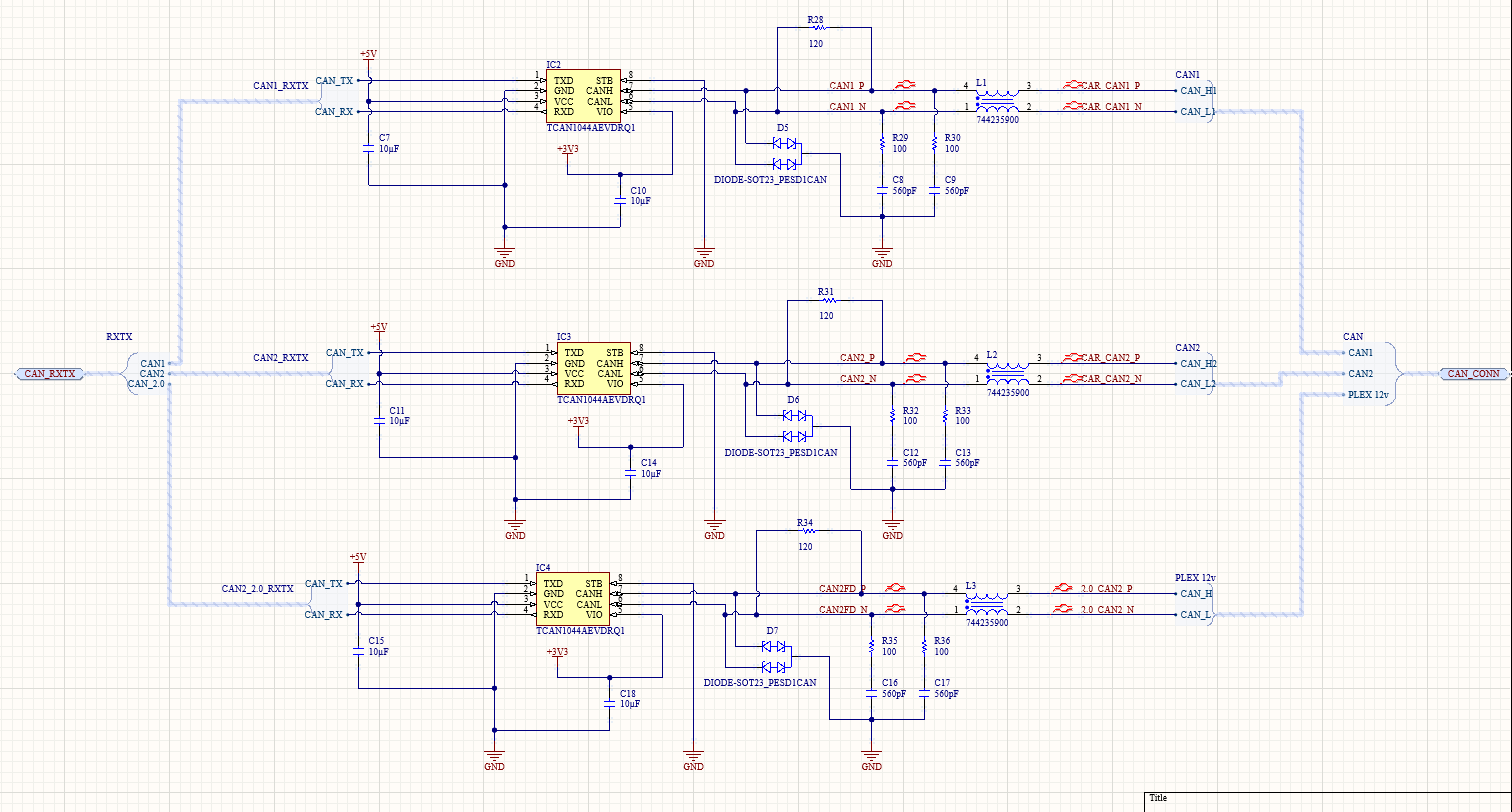
The board has 3 CAN transceivers: 2 which communicate with the car's internal buses, and 1 for private CAN to the display. Originally, the private CAN was point-to-point with the PLEX, but since the SAS has a 60 Ω termination inside of it, we moved it off of the main bus and onto my board's private CAN to protect the car-critical buses.

The dash PCB also takes in fault signals from the Safety Board which it uses to switch indicator lights on the Fault LED Buddy Board. It also has 5 auxiliary switches which are wired into the STM, and forwarded over CAN to the safety board to allow the driver to enable the car, cooling, Torque Vectoring, Traction Control, and "Party Mode".
Mechanical integration

The mechanical integration was defined by constantly shifting cockpit and controls packaging requirements. Working with our cockpit and driver ergonomics engineers, I redesigned and re-routed the board to fit the dashboard assembly within the monocoque and accommodate driver requests about interface locations and line of sight.
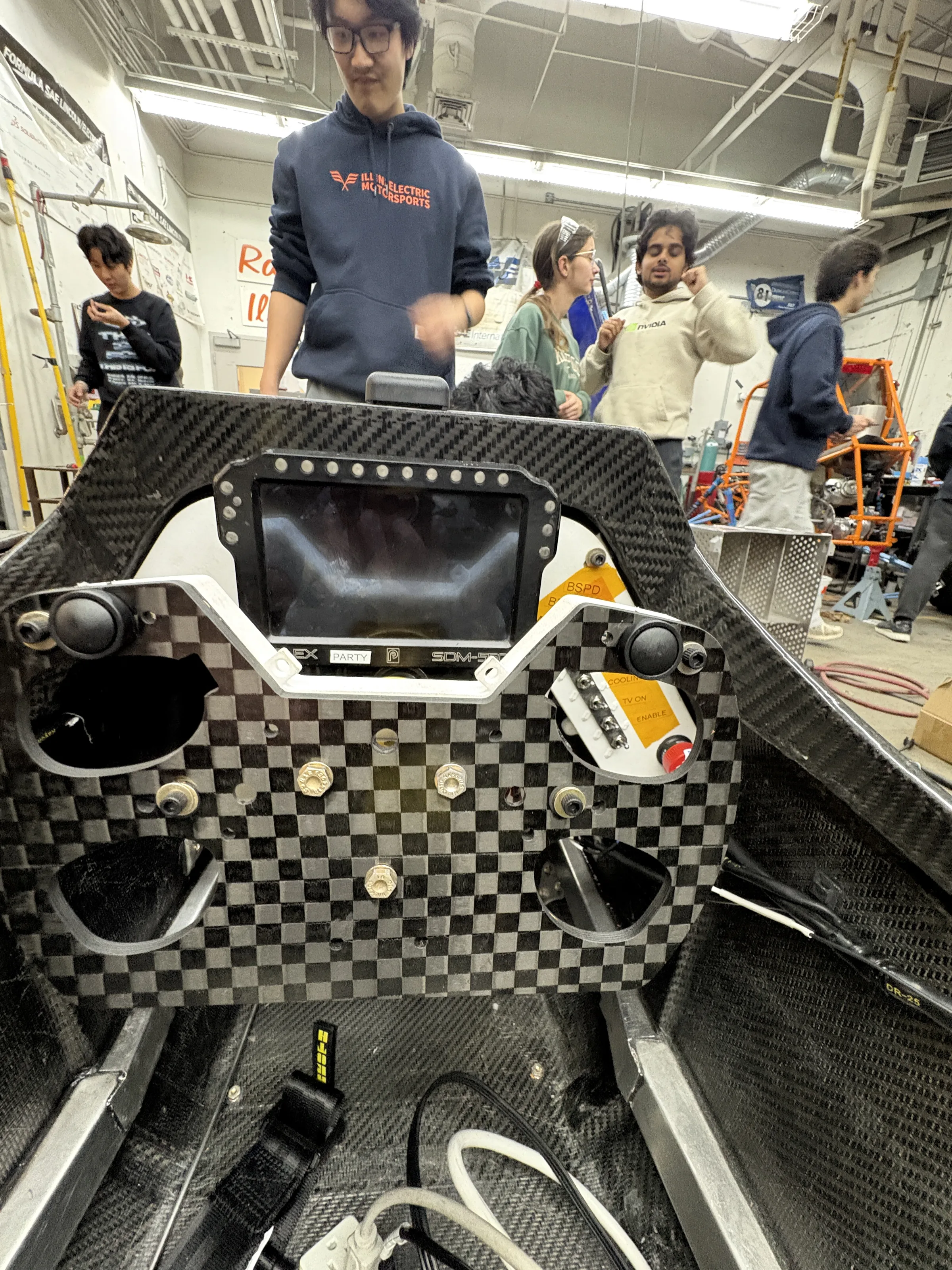
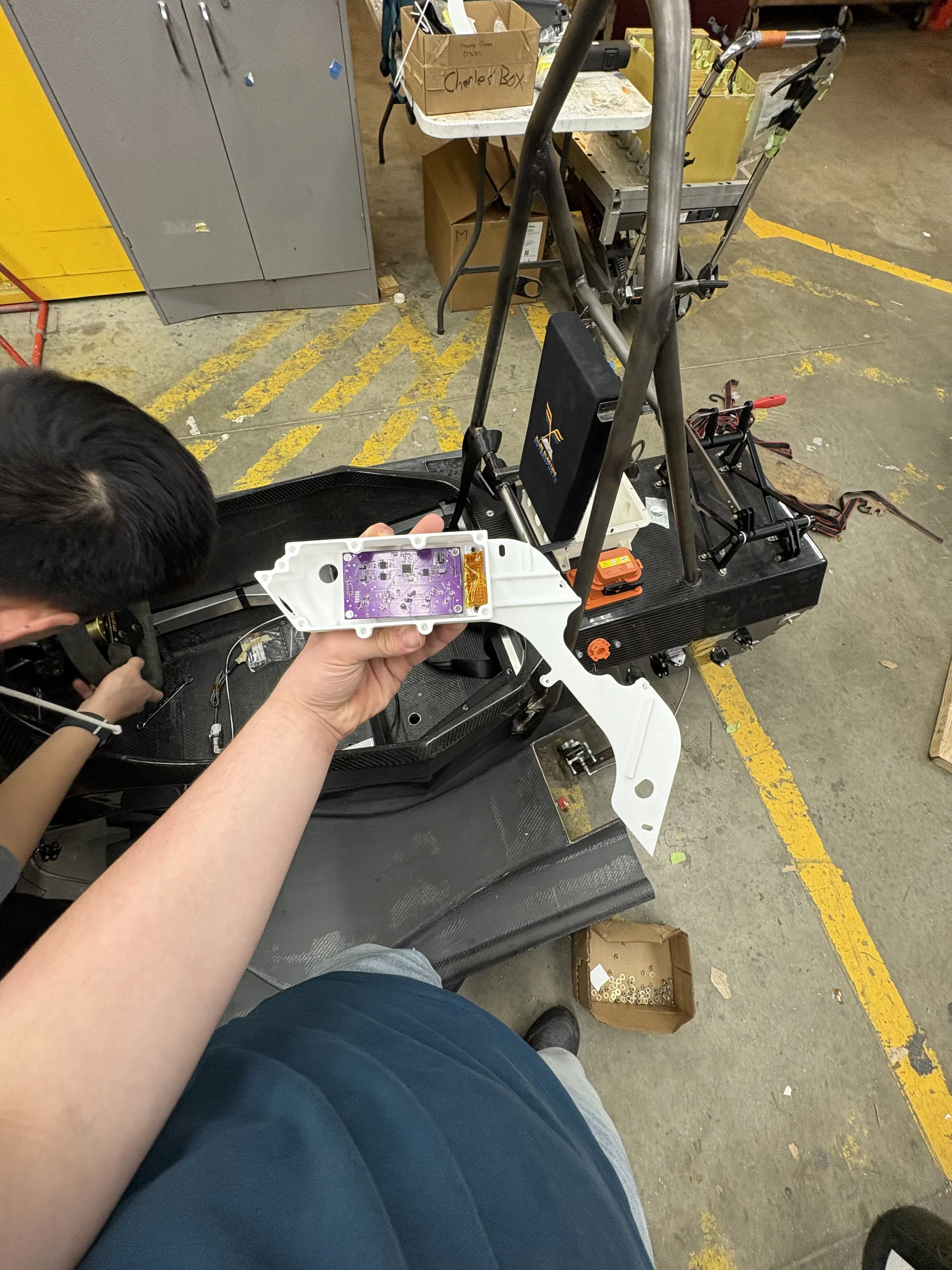
After the original design was completed, shifts in monocoque design and driver preference necessitated a 20% or more width reduction. By redesigning the layout from the ground up using everything I learned from my first attempts, I was able to increase the serviceability of the board and reduce its footprint by 23% compared with version 1.0.
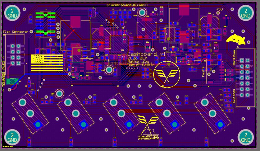
Purple Dash PCB layout showing routing, component placement, and the cockpit packaging constraints
PCB layout · routing and component placement
23% smaller board footprint
than version 1.0
02 / FORMULA SAE 2026

CAN signal integrity

One of the biggest shortcomings of our 2026 car's electrical architecture was an unoptimized CAN bus which struggled to support 2 Mbit/s CAN FD without dropping and corrupting some CAN frames. My goal over the summer was to compare what we did to industry standards and identify what shortcomings could be addressed.

Wire Harness Optimization

The most important thing for a successful CAN bus is to ensure that its harness is within spec for the specific baud rate and topology you choose to go with. Our prior design had many long stubs (length > 1 m). These cause unwanted reflections as the signals travel down a long stub, reach an unterminated end, and bounce back to impact the signal on the main bus. Per my calculations, the longest single unterminated stub we could run on our bus before it is physically incapable of transmitting data is 1.72 m \(\ell_{\mathrm{stub,max}}\approx\frac{\ell_{\mathrm{critical}}}{3}=\frac{t_{\mathrm{transition}}}{6\tau_{\mathrm{cable}}}\), and if you account for the fact that we have >20 stubs across the car and are running a CAN FD bus at 2 Mbit/s, this limit drops down to <30 cm.

Distributed Node Capacitance

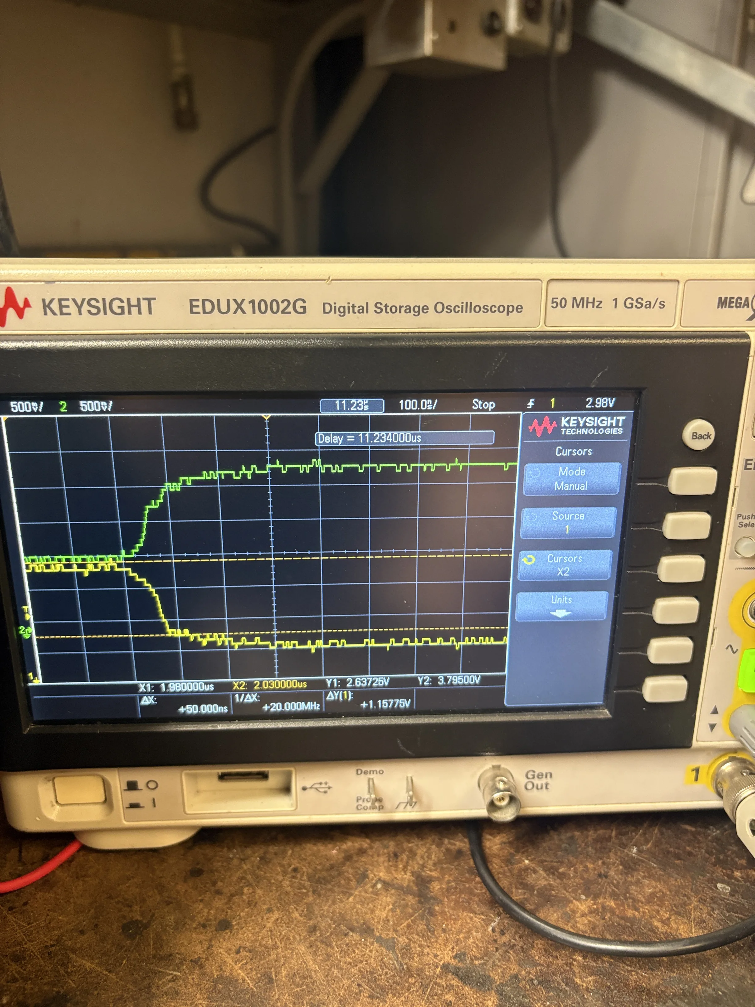
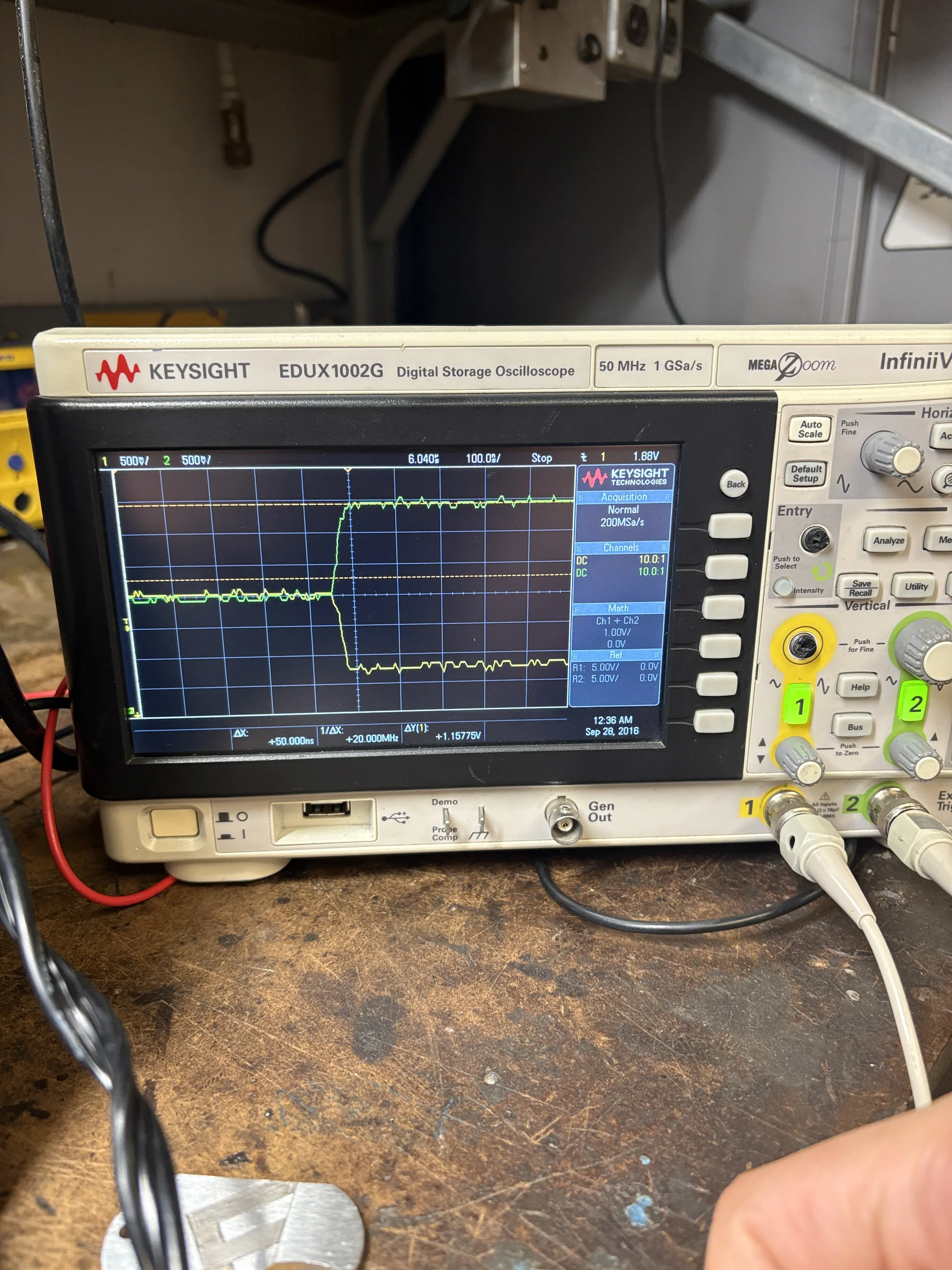
High node capacitance causes issues on our bus for two major reasons: increased capacitance increases the rise time of our bus, and if the local capacitance is high enough, it can drop the impedance below \(0.71Z_0\) which will start to impact CAN arbitration. Our previous schematics had a node capacitance of approximately 158.99 pF, an order of magnitude higher than what we would expect on a CAN bus. This degraded rise time and meant the minimum node spacing was 3.24 m which is significantly larger than what we see on car. By implementing new CAN schematics, I was able to reduce node capacitance to 24.72 pF (an 84.5% reduction) which allows us to space our nodes 50 cm apart.

\(d_{\min}\approx\frac{C_{\mathrm{node}}}{0.98C_{\mathrm{cable}}^{\prime}}=\frac{24.72\,\mathrm{pF}}{0.98(50\,\mathrm{pF/m})}\approx0.50\,\mathrm{m}\)

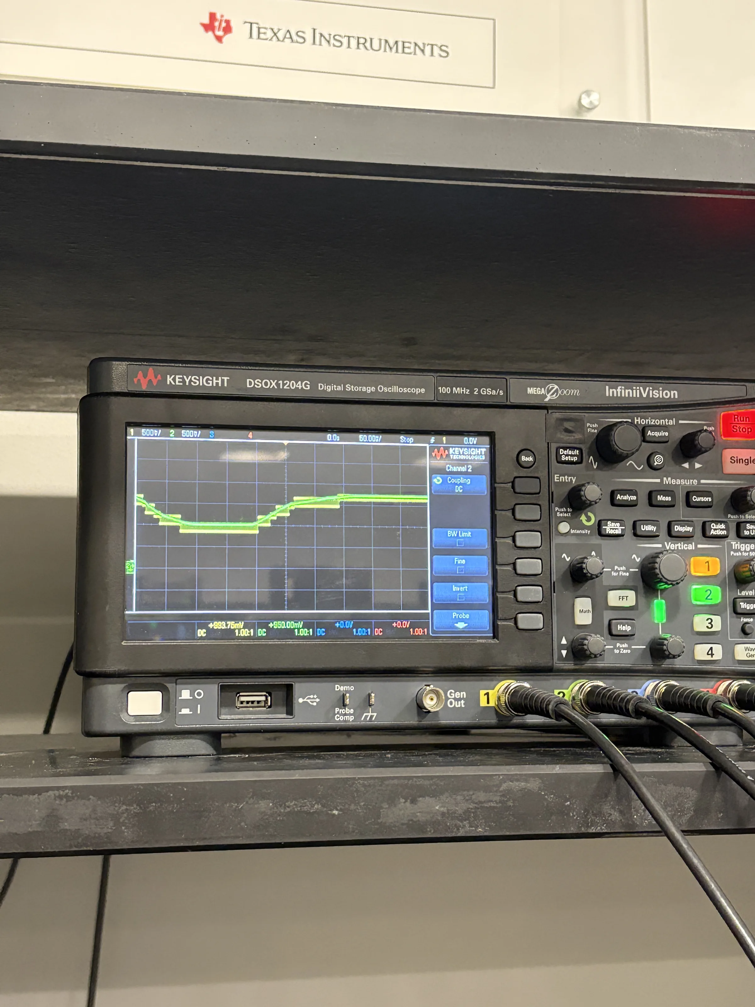
Oscilloscope capture of CAN rise time before filter changes
● Before filter changes
Oscilloscope capture of CAN rise time after filter changes
● After filter changes

IEM Standard CAN Reuse Block

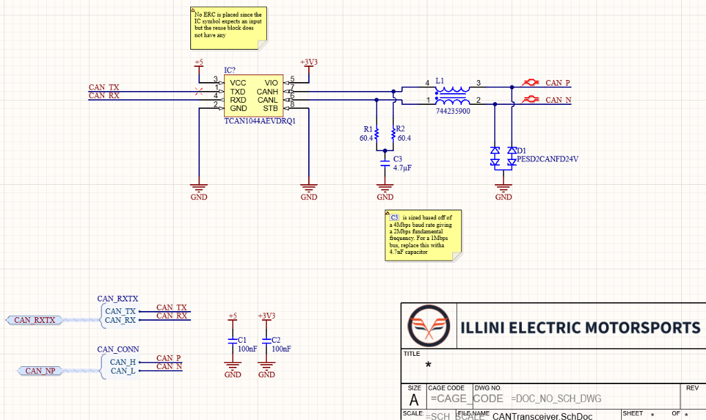
Reducing this capacitance came at the cost of removing the per-line low-pass filters we had on previous CAN schematics. To ensure that we have enough noise rejection, and to comply with industry standards, I also implemented split termination into our standard reusable CAN schematic. This helps to mitigate interference by placing a capacitor to ground in the midpoint of the termination. This capacitor acts as a low-pass filter which shunts high-frequency common-mode noise to ground without impacting our differential signal.

Utilizing all of the information I gained from this research, I designed a new standard CAN reuse block which is now on the schematics of each of our car-critical PCBs. This schematic supports a 4 Mbit/s baud rate so we can run even more telemetry data to improve our vehicle control algorithms and prepare for autonomous racing.

Complete CAN transceiver reuse schematic developed as an output of the filtering and bus-loading trade study
Trade-study output · reusable CAN transceiver circuit

Analysis based on my CAN/isoSPI study; transmission-line model and spacing approximation reference TI SLLA270.

03 / ECE 145 2026

Analog Swerve

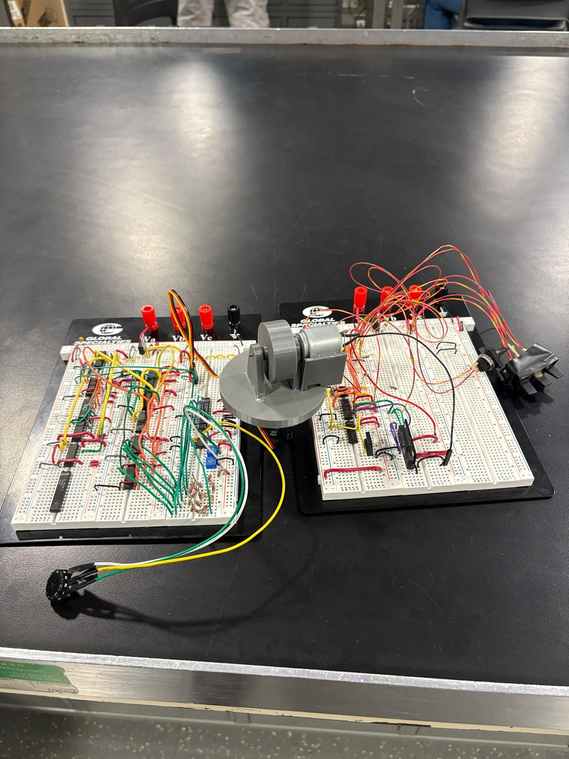
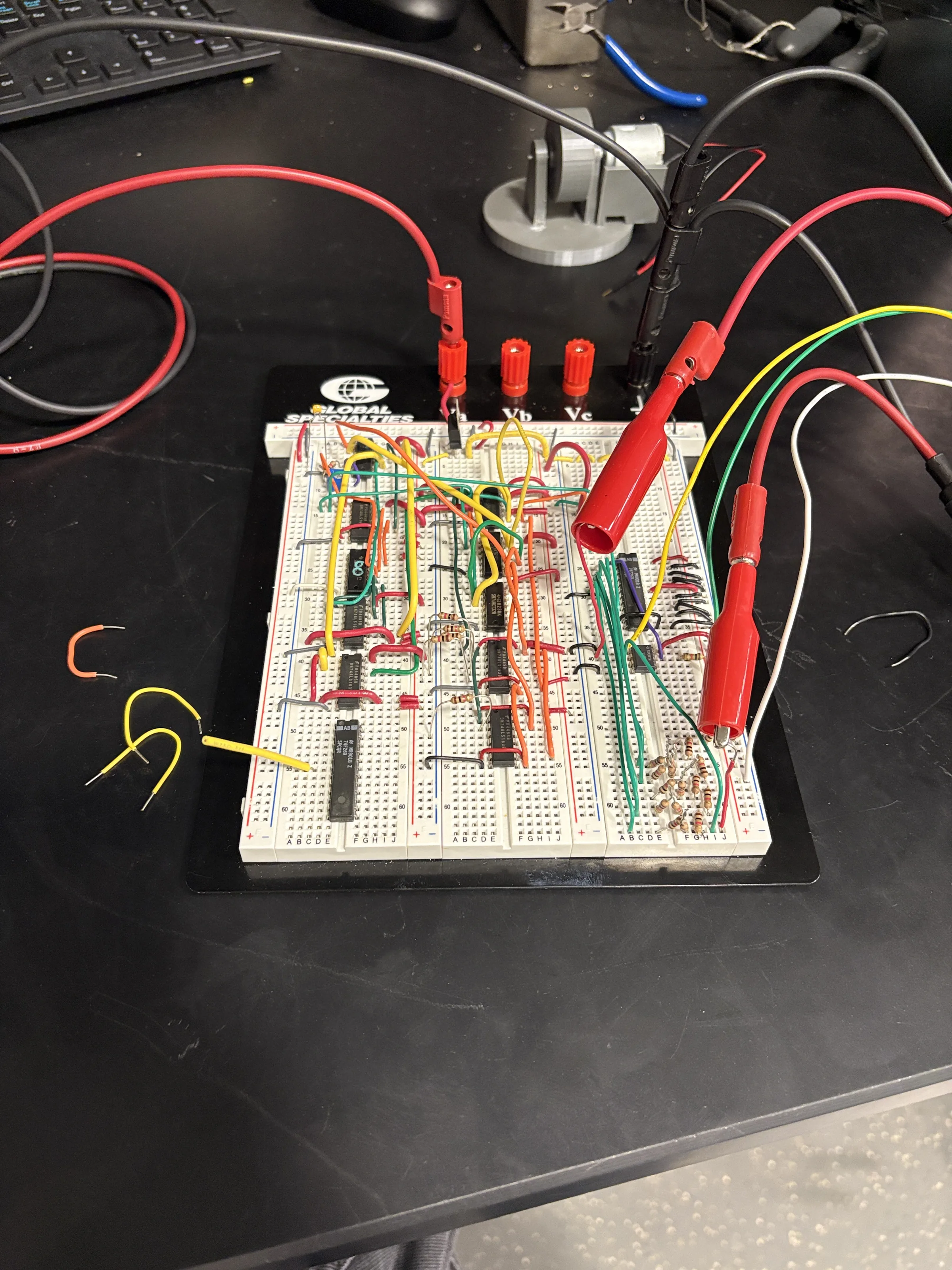
For ECE 145: First-Year Design Laboratory, I was tasked with designing something using only hardware components to solve some sort of problem. From my background in FRC robotics, I have always been interested in holonomic drivetrains and their feasibility to navigate terrain. I designed a completely hardware-controlled swerve module with independent position and speed control.

Complete analog swerve prototype with drive motor, steering servo, and both control breadboards
Assembled proof of concept · motors and breadboard controls
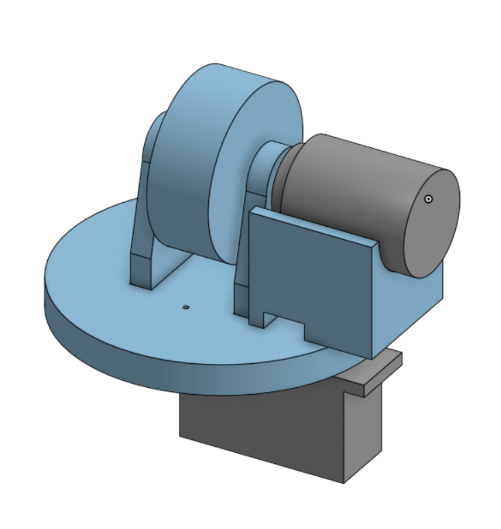
CAD model showing the swerve module wheel, drive motor mount, and steering servo
Module CAD · wheel, motor mount, and steering assembly

Drive control

An R-2R ladder DAC converts the digital speed commands into an analog control voltage. That voltage drives a 555 timer to change a PWM duty cycle sent to the DC motor which controls the speed output. Using an H-bridge setup, I was able to implement a direction bit which controls which way the module was headed, and an extra control bit was added to enable or disable driving for safety.

Steering control

To control the angle of the wheel, I went with an off-the-shelf servo motor to limit the scope of the project. I generated a 10 kHz square wave and used cascading timers to step that down to the frequency necessary for the PWM envelope that controls a servo. A separate counter based on the original 10 kHz pulse defines the width of the PWM pulse which directly maps to an angle.

To control the angle, I wired up a potentiometer to a tracking ADC I built to decode the angle into specific bits I could feed into my counter. This worked by creating another R-2R ladder DAC whose output is compared by a comparator to the input. If the DAC's output is lower than the voltage, the counter wired up to the DAC is incremented, and vice-versa if the output is above the input voltage. This allows the counter to accurately track the input voltage down to a single bit of error based on the accuracy of your ADC. Varying that pulse width changes the steering angle without changing the frame timing.

04 / Personal project 2024

Voron Printer

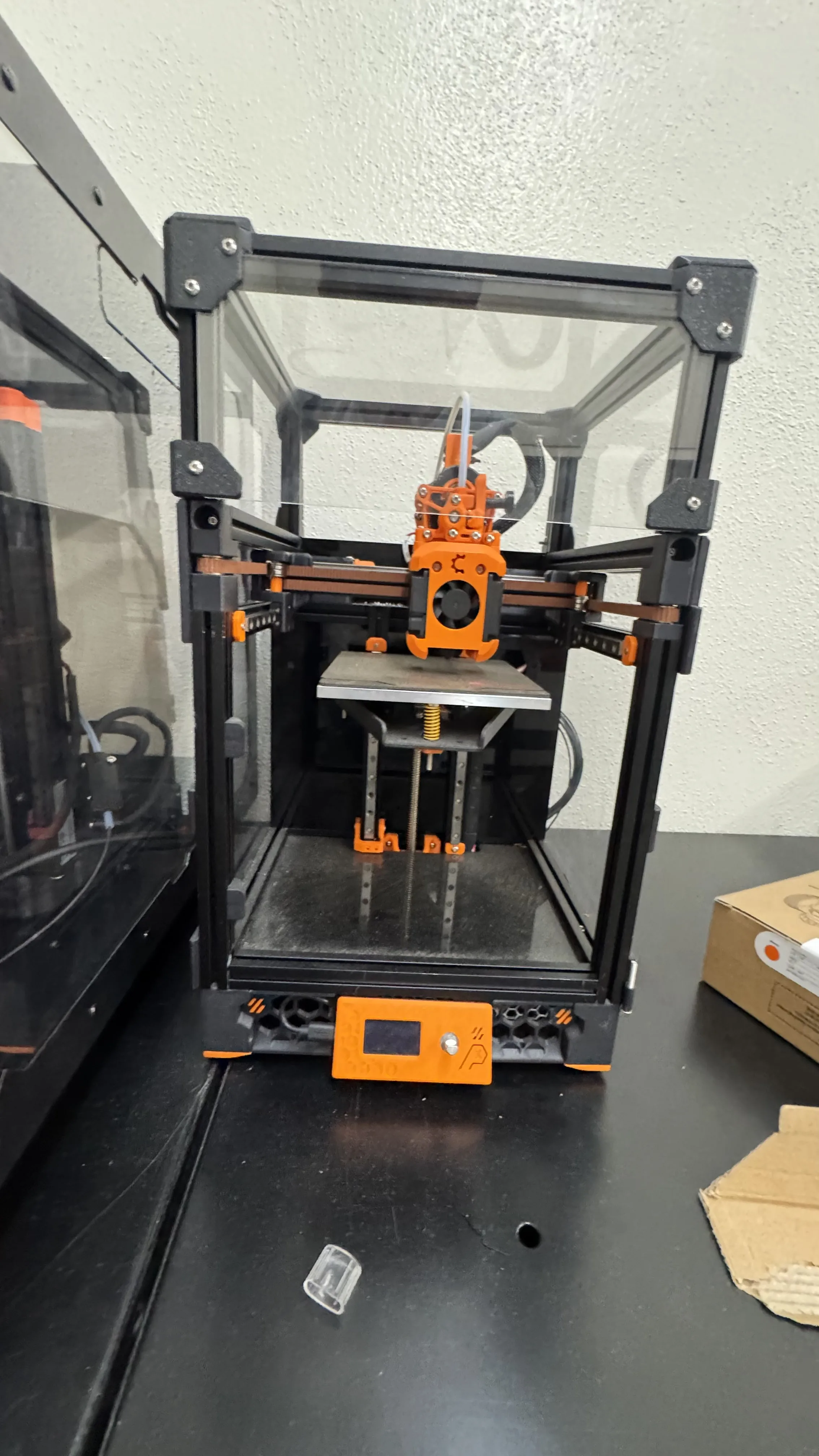
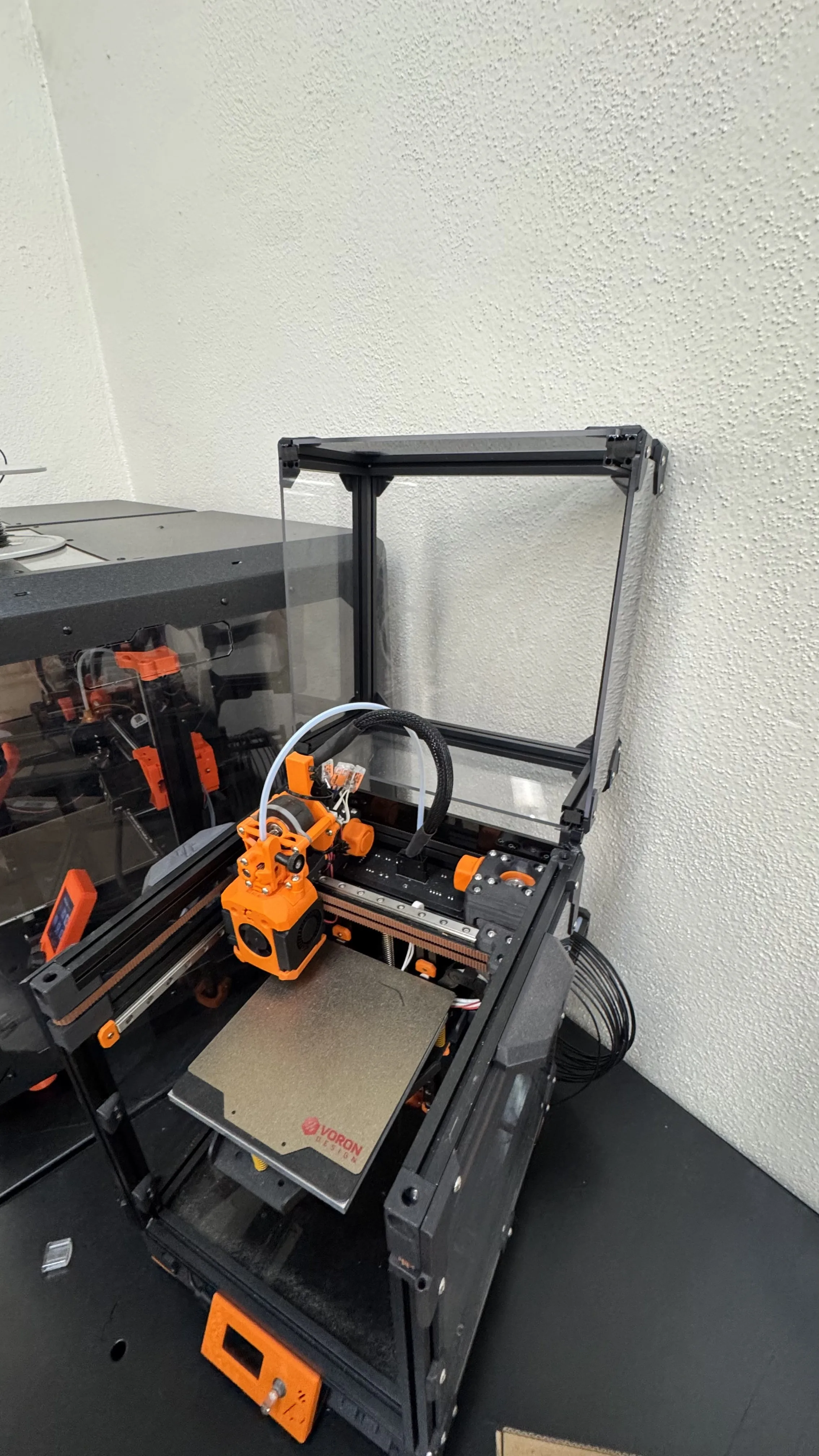
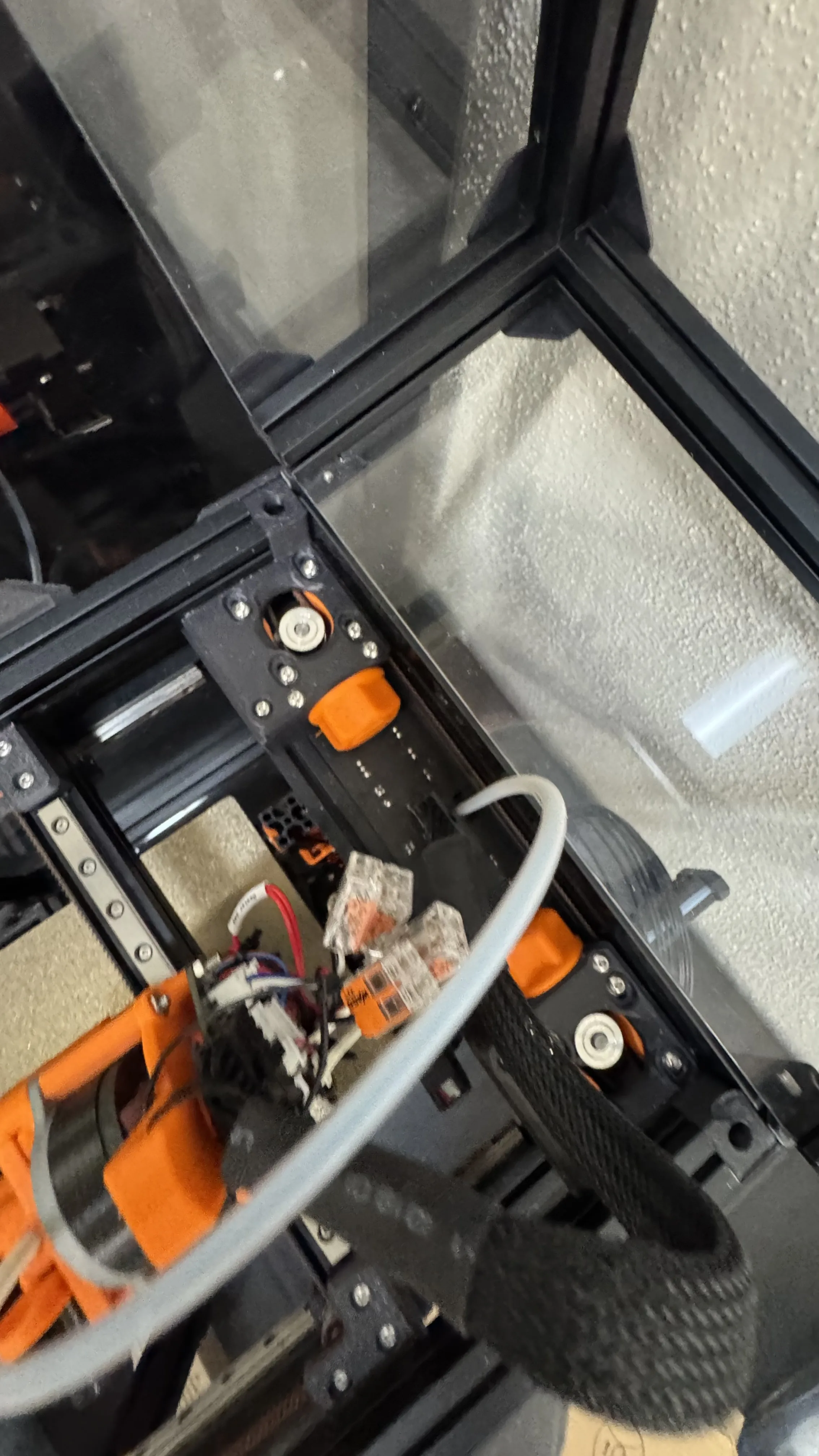
To support the manufacturing capabilities of my robotics team, and allow me to quickly prototype my own designs, I built my own Voron 3D printer out of readily available COTS parts, aluminum extrusion, and 3D-printed components. To simplify wiring and improve signal integrity I implemented CAN bus for toolhead communication, and to maintain chamber temperature, I tuned a PID controller with feed-forward to rapidly heat or cool the chamber while accounting for error.

Completed orange and black Voron V0 printer built for the robotics team
Voron V0 · assembled printer

To increase print consistency and lift the speed cap of the printer, I tuned input shaping characteristics to account for ringing and vibrations as the printer executes G-code. This allows the printhead to move faster and cancel out vibrations with its own motion to push accels.

05 The kitchen

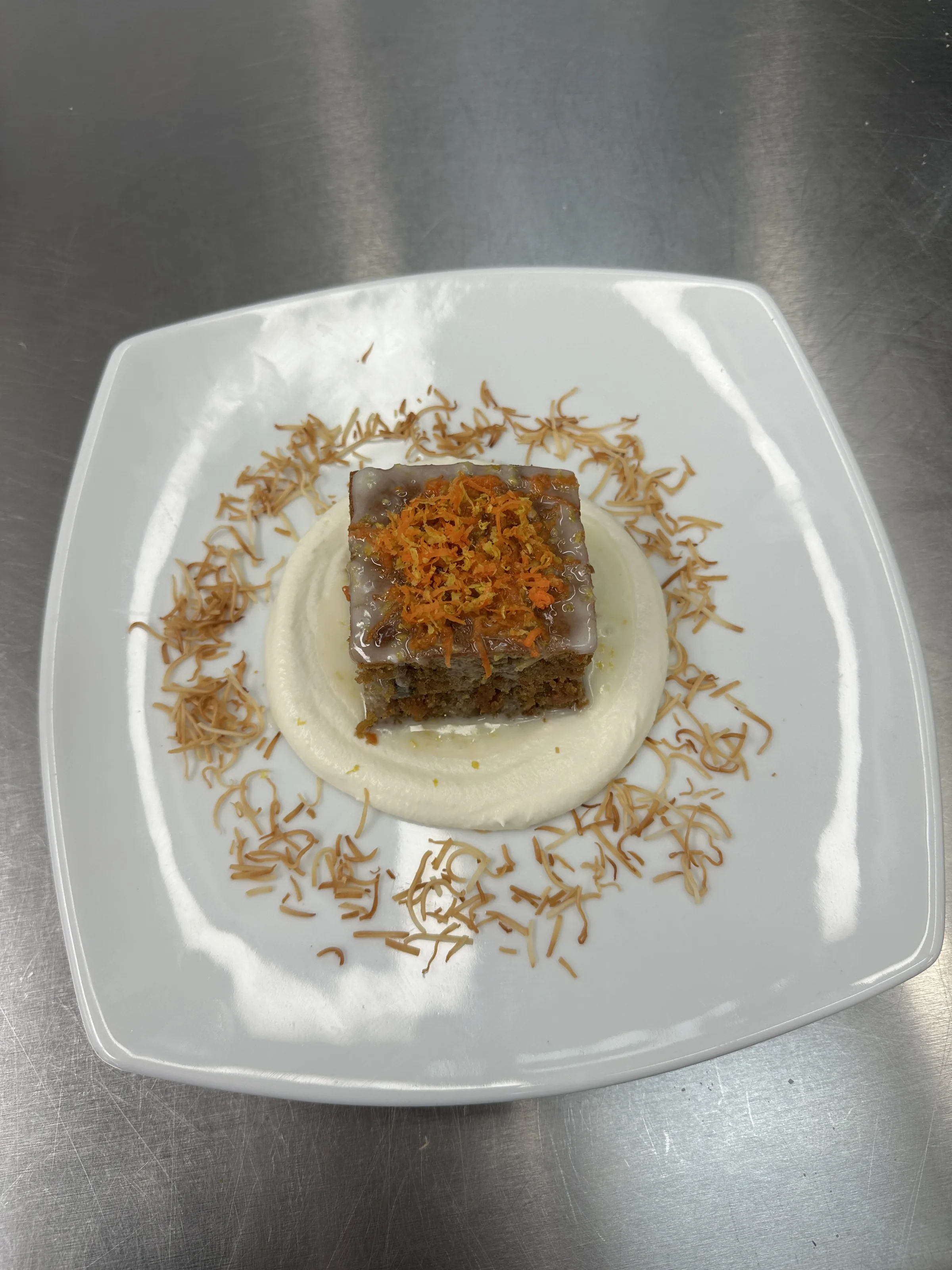
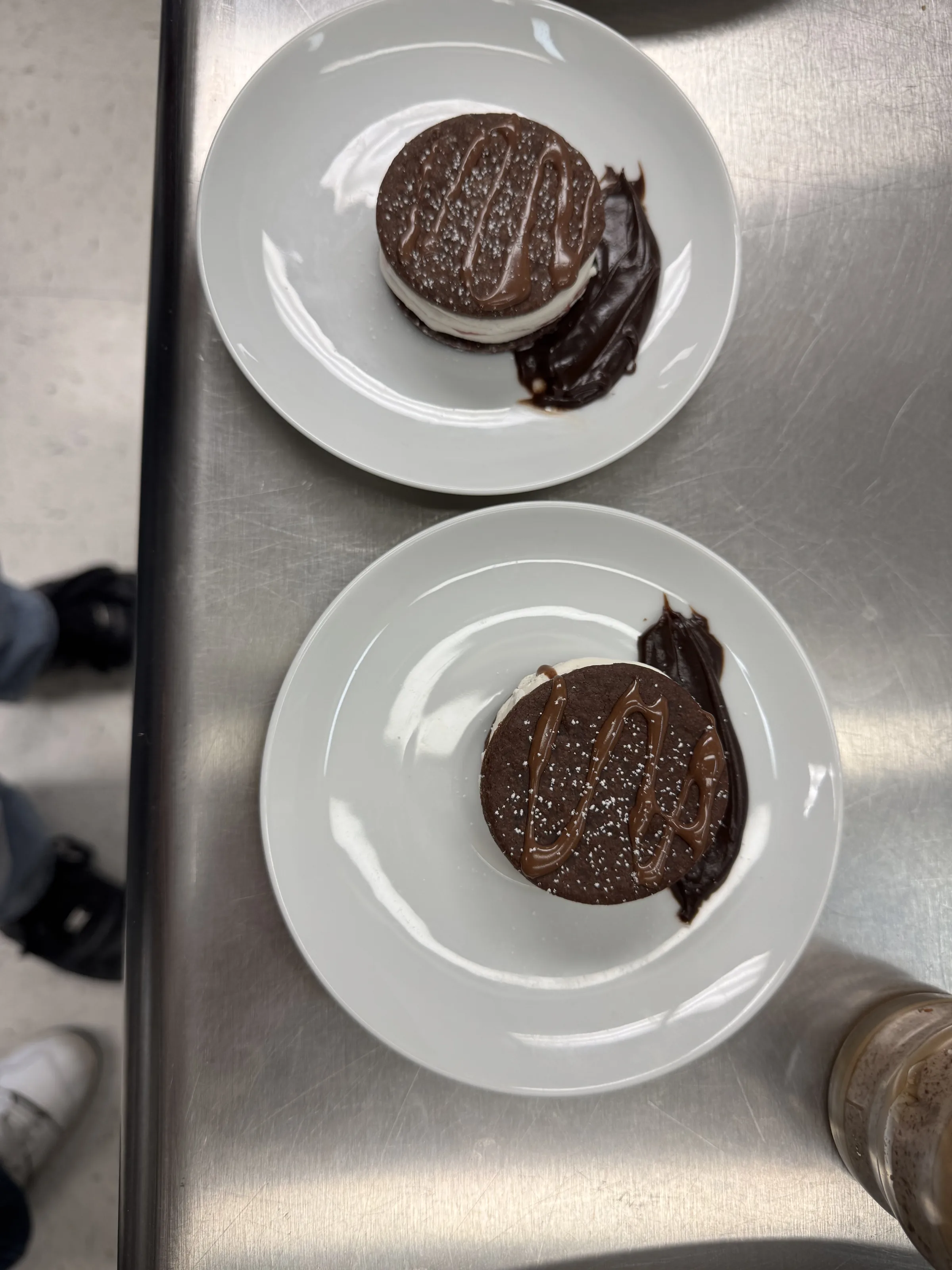
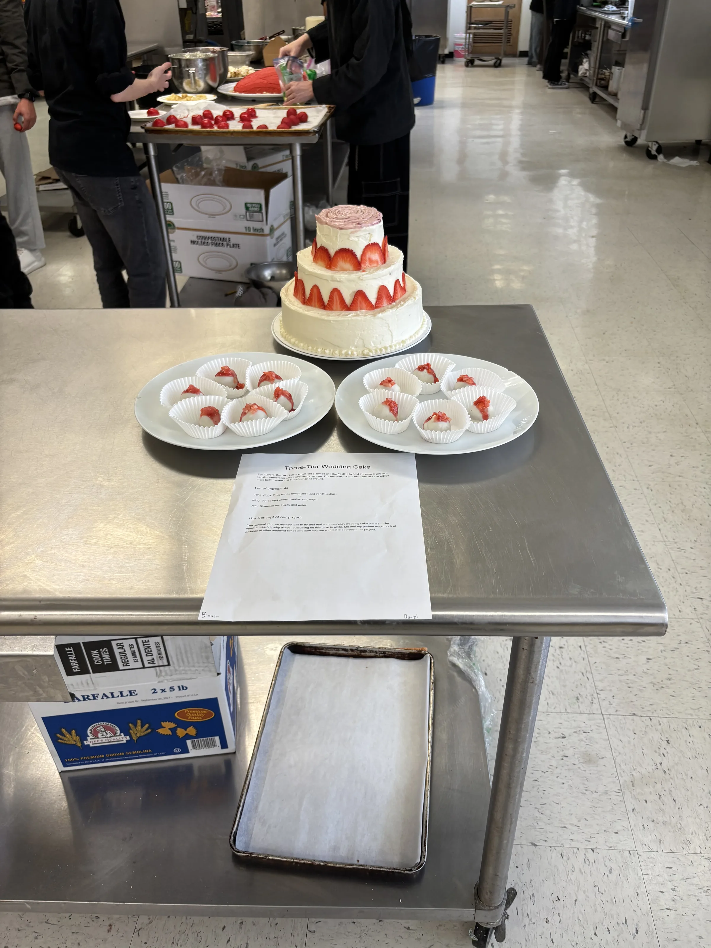
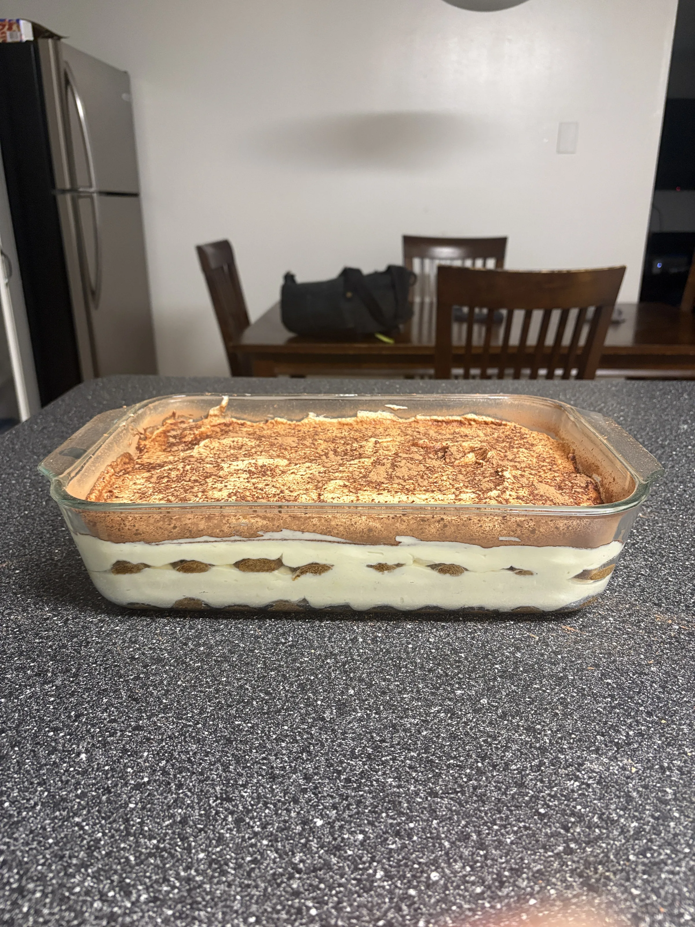
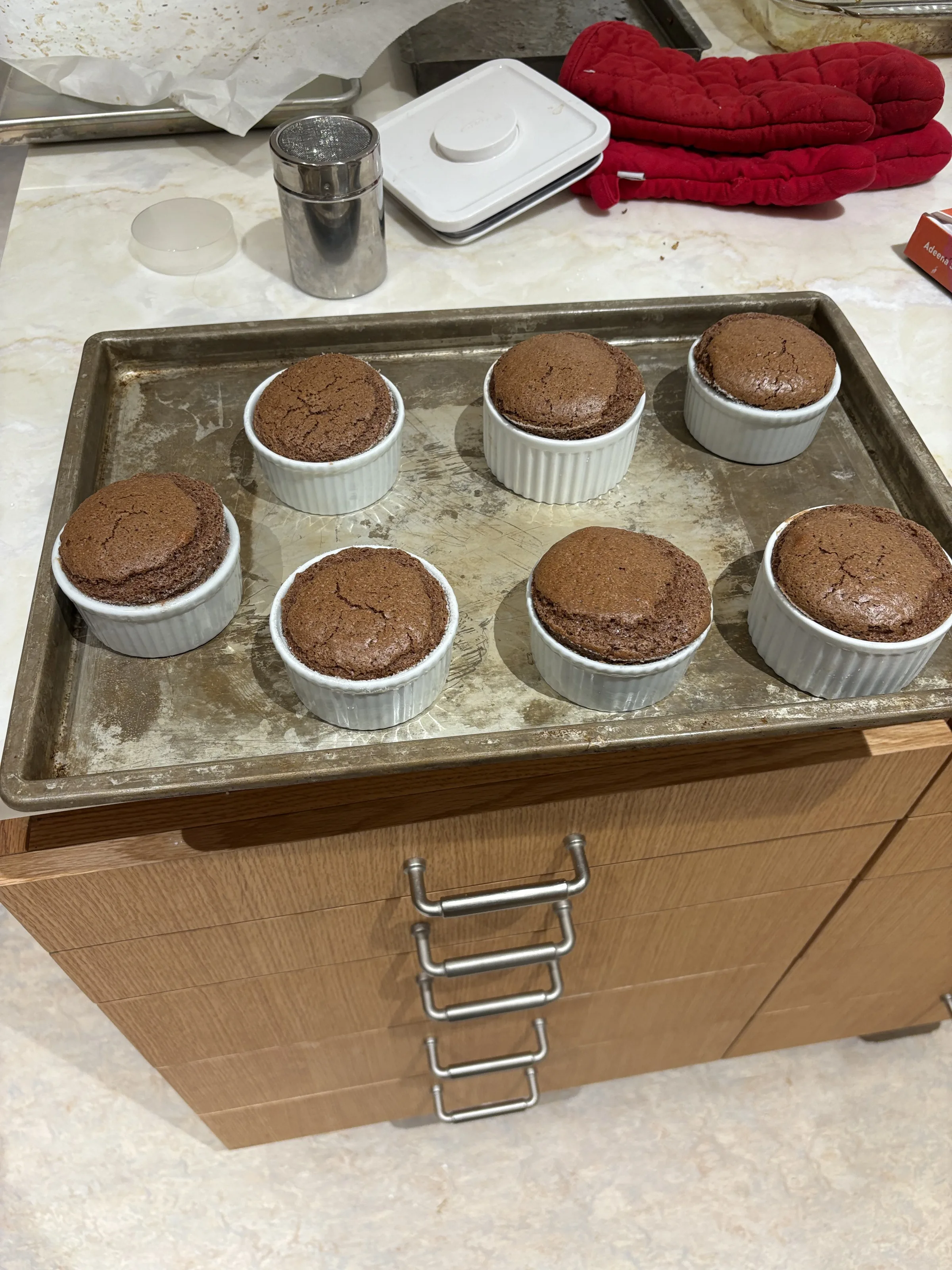
Assorted Baked Goods

Outside of the lab, I love to bake. I can unwind with a low-stakes project which still lets me express some creativity and technical skill, and at the end I am able to share the enjoyment with my friends.

Selected project image